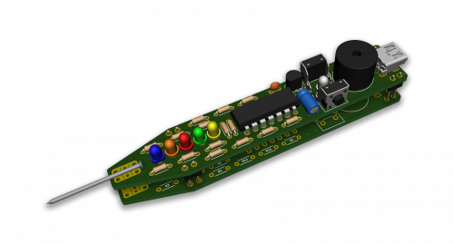
Logic and Level Probe
What is the PICKitPlus Logic and Level Probe (LLP) ?
The LLP enables the simple measurement of a voltage or signal, touch the target with the probe and the LLP will indicate the type of signal, and a buzzer will respond.
The LLP supports:
- High/Low signal detection - the standard logic probe function
- Approximate voltage measurement
- Detection of oscillating signals
- Configurable multi-tone buzzer
- Wide input voltage range (0V to 30V)
- Wide supply voltage range (4.5V to 12V)
- Suitable for left- or right-handed use
- USB power connector
- JST power connector
Logic Mode
When used in Logic Mode the yellow and blue LEDs will illuminate to indicate a high or low signal, respectively. If sound is enabled, a tone will also be emitted. A signal of 1.8V or greater is considered high, while 1.5V or lower is considered low. Between 1.5V and 1.8V are not valid logic signals, and no colours are shown. If an oscillating signal (greater than about 40Hz) is detected, the red LED will illuminate and a different tone will sound.
Level Mode
When used in Level Mode the approximate voltage of the signal will be displayed using the LEDs. If the measured voltage is between two values both LEDs will be ON. Voltages in excess of around 12.5V will show all five LEDs. Voltages greater than 14V are considered “out of range”, and all five LEDs will flash. When sound is enabled, a tone will be emitted. This tone will vary in pitch to reflect the sensed voltage.
Specifications
| PARAMETER | SPECIFICATION |
|---|---|
| Logic 1 | ≥ 1.8V |
| Logic 0 | ≤ 1.5V |
| Input signal voltage | 0V - 15V (but will survive up to 30V) |
| Power supply range | 5 - 12 V |
| Input impedance | 39KΩ (approx) |
| Supported oscillation waveform | square, sine, triangle |
| Oscillation detection frequency |
35Hz ~ 1.2Khz PWM signals at extremely low or high duty cycles may not be accurately detected at the extreme ends of the supported frequency range |
An assembled LLP

Assembly
This is a self assembly kit. It should take 60 minutes to assemble. The assembly is simple and is an easy process.
For the full assembly instructions - see here
Buying
If you want one see our buying page and select the Logic and Level Probe and we can get you started with the fun of building your own Logic and Level Probe.